














How is an emergency-stop switch wired to a safety relay?
The emergency-stop is arguably the most important control element on any machine: in the event of danger, a single press of the button must reliably bring the machine to a safe standstill. For this to work, the switch alone is not enough – it must be correctly wired to a safety relay and the downstream contactors. This article explains, step by step, how this safety chain is set up and what is important when it comes to wiring.
Emergency-stop or emergency switch-off – what is the difference?
The two terms are often used interchangeably in everyday language, but they refer to two different functions:
- An emergency-stop brings the machine to a controlled, safe state and safely shuts down the affected part of the system. Once activated, the button locks and must be unlocked by turning or pulling before a restart is possible.
- An emergency switch-off disconnects the system from the power supply. As the machine is not first brought to a safe state, a residual hazard may still exist under certain circumstances.
In the practice of machine safety, the emergency-stop function predominates. The wiring to a safety relay is, in principle, identical in both cases.
What a safety relay does
A safety relay (also known as a safety switching device) is placed between the emergency-stop button and the contactors that actually cut off the hazardous power. It performs three tasks:
- It continuously monitors the emergency-stop contacts for faults.
- It shuts down as soon as the button is pressed by opening its safety outputs.
- It only re-enables the system after a controlled reset – thus preventing an unintended restart.
Single- or dual-channel: why redundancy matters
For simple applications, an emergency-stop can be connected via a single channel. For higher safety requirements, however, it is wired as a two-channel system : two independent normally closed contacts each feed one input channel of the relay.
This redundancy – combined with the relay’s short circuit monitoring – detects a wire break, a welded contact, or a short circuit between the two channels. This is precisely what is required to achieve Category 3 or 4 and Performance Level d or e in accordance with EN ISO 13849-1.
Step by step: Connecting the emergency-stop to the safety relay

Terminal designations vary depending on the manufacturer. You should therefore always wire your relay in accordance with its respective data sheet. As an example, the configuration looks like this:
- Connect the power supply
- Wire channel 1 – from the channel-side source terminal of the safety relay via the first normally closed contact of the emergency-stop back to the input of channel 1 (e.g. 11-12).
- Wire channel 2 – in exactly the same way via the second normally open contact to the input of channel 2 (e.g. 21-22). Many devices supply the two channels from different clocked outputs so that a short circuit between the channels can be detected – follow the data sheet precisely in this regard.
- Set up the reset – connect a momentary NO contact (reset button) via the reset terminals (e.g. 13-14). With a monitored manual reset, the relay only energises when the button is released; this detects a stuck or bypassed reset button.
- Route outputs to the contactors – the two normally open safety outputs of the safety relay (e.g. 13–14 and 23–24) control two separate contactors, LS1 and LS2, which switch the motor power. Two contactors in the power path ensure redundancy.
- Close the feedback loop (EDM) – connect the mechanically linked mirror contacts (NC) of LS1 and LS2 in series to the reset/feedback loop. If a contactor becomes welded, its mirror contact remains open and the relay can no longer be reset. This ensures that a faulty contactor is reliably detected.
This is how the circuit behaves during operation
If the emergency-stop button is pressed, both channels open, the relay de-energises, the safety outputs open and channel 1 and channel 2 de-energise – the power is switched off. Simply unlocking the emergency-stop switch does not have any effect: the circuit remains safely de-energised until the reset button has been pressed and released.
Stop category 0 or 1?
Before wiring, the stop category in accordance with EN 60204-1 should be determined:
- Category 0 – immediate power cut-off (as in the example above).
- Category 1 – controlled shutdown with subsequent power cut-off; requires an additional time relay or a drive-controlled stop function, thereby altering the wiring.
The required category is determined by the risk assessment for the machine in question.
What matters in the contact element
However robust the evaluation in the relay may be – it can only operate as reliably as the signal supplied by the contact element. Three characteristics are crucial:
- Positive opening in accordance with EN 60947-5-1, Annex K: The normally closed contact is mechanically forced to open, even if a contact should become welded.
- Switching of low currents: Modern electronic safety relays operate with pulsed outputs and very low test currents. The contact element must be able to switch these low currents reliably.
- Self-monitoring: Contact elements that trigger themselves in the event of mechanical damage or if the contact element becomes separated from the actuator fill a gap that the relay circuit alone cannot cover.
Suitable components from Schlegel
To meet precisely these requirements, Georg Schlegel GmbH & Co. KG offers a comprehensive range of products “Made in Germany”:
- Positive opening contact blocks, single- or dual-channel (EN 60947-5-1, Annex K) – suitable for single- or two-channel evaluation by any standard safety relay.
- Switching of low currents from 5 mA at 24 V and below – compatible with clocked inputs of electronic safety switching devices.
- Self-monitoring emergency-stop contact blocks that trigger themselves in the event of incorrect installation or damage.
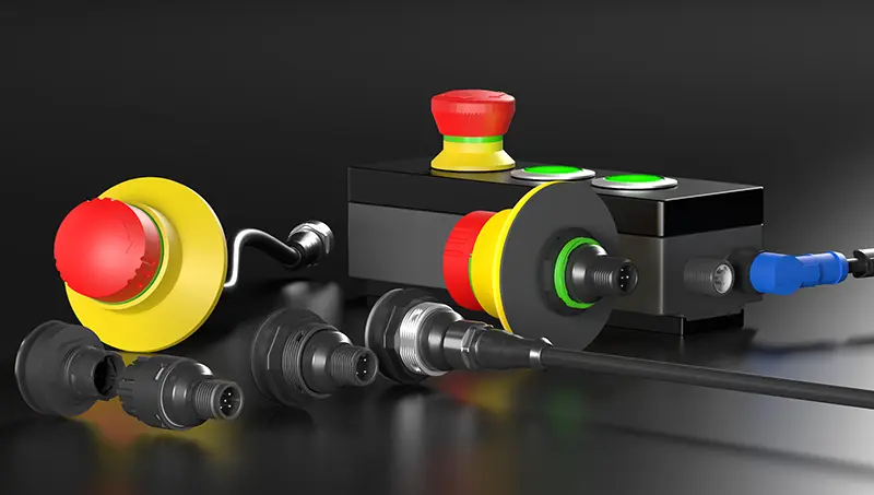
- Emergency-stop with illuminated active/inactive status indicator (in accordance with EN ISO 13850:2015) – prevents confusion between active and inactive buttons on detachable control panels.
- Pre-assembled emergency-stop and reset pushbuttons in enclosures for the monitored reset input.
- AS-Interface “Safety@Work” as an alternative to discrete relay wiring.
- Robust designs (mounting holes Ø 16.2 / 22.3 / 30.5 mm and square variants), IP protection ratings IP65 to IP69K, twist or pull release – TÜV and UL approved, certified to EN 60947-5-5 and DIN EN ISO 13850.
Checklist: Standards and validation
Before using the safety function:
- Carry out a risk assessment and determine the required Performance Level (EN ISO 13849-1) or SIL (EN 62061).
- Select the stop category in accordance with EN 60204-1
- Position the reset outside the danger zone, with a clear view of the danger zone (EN 60204-1).
- Remember: The emergency-stop is a supplementary protective measure – it does not replace isolating or interlocked safety guards.
- Use contactors with mechanically linked (mirror) contacts; otherwise, the feedback circuit may fail to detect a welded contact.
- Validate the safety function: test the button, each channel individually, test a simulated wire break and a jammed contactor – and have the system approved by a qualified electrician.
Conclusion
An emergency-stop is only safe if the entire chain is correct: a positively opening, redundant contact block at the input, monitored evaluation in the safety relay and redundant load disconnection with a feedback loop at the output. By ensuring that the the contact block is positive opening (NC), capable to switch low currents and self-monitoring, you lay the foundation for a standard-compliant and reliable safety function.
Are you planning a specific application? The Product configurator from Schlegel allows you to put together the right emergency-stop switch with the correct contact block.

